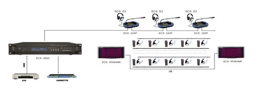
1. Fully digital wireless transmission technology. System conforms to IEC61603, part 7.
2. 2-8MHz frequency band eliminates disturbance from all types of lighting systems.
3. The system provides multi-channel 4/8/12/16 for option
4. High security, prevent external interference.
5. Elegant configuration in accordance to ergonomics.
6. 160x32 dot matrix LCD display system information
7. Installation: 19-inch frame
Model |
SCS-360M |
Modulation frequency |
Carriers 0 to5: 2 to 6 MHz, according to IEC 61603 part 7, Carriers 6 and 7: up to 8MHz |
Protocol and modulation |
DQPSK, according to IEC technique 61603 part 7 |
Audio frequency response |
20Hz-10kHz (-3dB) at standard quality |
Total harmonic distortion at 1 kHz |
<0.05% |
Crosstalk attenuation at 1 kHz |
>80dB |
Dynamic range |
>80dB |
Weighted signal-to noise ratio |
>80dB(A) |
Power consumption |
Operating:100W; Standby: 25W |
Asymmetrical audio inputs |
+3 dBV nominal, +6dBV maximum(±6dB) |
HF output |
1 Vpp, 6VDC, 50Ohm |
Interpreter console connector interface |
12P-DIN |
Audio input |
RCA x16 |
Audio output |
RCA x16 |
HF output connector interface |
BNC x 4 |
Operating temperature range |
0-40 degree |
Power supply |
AC110V-200V ~ 50Hz-60Hz |
Dimensions |
485×355×90mm |
Mounting |
19” rack mounting |
N.W |
8kg |

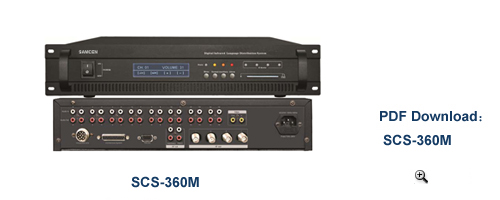
1) Power on/off switch: Power switch (Press I to turn on the power, power indicator is lighting, press O to turn off the power)
2) Menu display LCD: The LCD-display gives information about the transmitter status. It also use as an interactive display for configuring the system)
3) Transmitter communication LED: This LED is used for display the system communication status, if the communication properly, the LED will flashing rhythmically, if the LED stop flashing during working, the transmitter may has problem.
4) Menu button: To operate the configuration system inputs/languages/safety settings, etc.
5) Normal button: To setting the normal working status—interpretation, the corresponding LED is green.
6) Auxiliary button: To setting the auxiliary working status—music, the corresponding LED is orange.
7) Alarm button: To setting the alarm working status—emergency time, the corresponding LED is red.
8) Management card LED: the LED wills lighting when management card correctly insert.
9) Management card interface: User must insert the correct card during setting
10) Mini IR-radiator: Four IREDs, transmitting the same infrared signal as the radiator output. This can be used for monitoring purposes.
11) Interpreter connector: Use for connection interpreter consoles
12) Conference connector: Use for connect compatible conference system
13) RS232 interface: Use for connect computer.
14) Auxiliary audio inputs: Female RCA connector for external audio inputs to connect auxiliary audio signals such as music, floor language or emergency audio signal
15) Emergency audio inputs: Female RCA connector for emergency audio signal, when this function available, system will distribute the emergency audio signal to all output channels and overriding all other audio inputs.
16) HF signal output: Four HF BNC connectors, used to connect the radiators. Up to30Radiators can be loop-through connected to each output.
17) Audio signal output: 4/8/12/16 audio connectors to connect other audio equipments. The number of connectors depends on the transmitter type
18) Audio signal input: 4/8/12/16 audio connectors to connect external unbalanced audio input signals. The number of connectors depends on the transmitter type.
19) Power supply: The transmitter has automatic voltage selection. A power cable is provided.


